Home
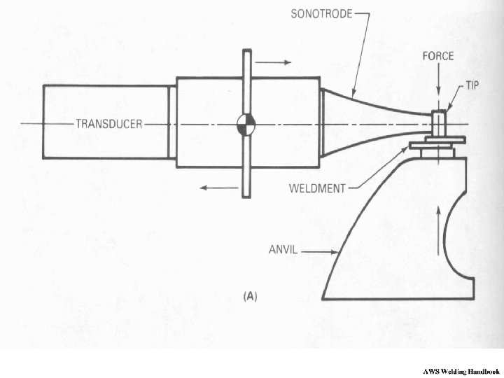
Ultrasonic Welding Machine Diagram . This potential danger is easily reduced by enclosing the ultrasonic welding machine in a safety box or cage and/or using ear protection. The parts to be welded are placed in the anvil or fixture.
Ultrasonic Welding Definition Of Ultrasonic Welding A Solid from slidetodoc.com This is a great tool for understanding and optimizing the welding process. 7c52 welding set diagram wiring resources. Transducer is a device which can convert high frequency electric signal into high frequency mechanical vibration. The term ultrasonic is used to describe a vibratory wave of frequency above that of the upper frequency limit of the human ear, i.e. However, there are some machines which, except for certain minor changes, may be considered as a standard.
Ultrasonic welding ultrasonic welding is the most common application of ultrasonic assembly. Ultrasonic components diagram k v ultrasonic power supply converts 50/60 hz electrical cycles to 40 khz, 20 khz orr 15 khz electricall cycles or frequency. pressure motion metal parts ultrasonic horn transmits mechanical vibrations to the parts that are to be welded. Production rate while working on ultrasonic welding equipment is quite high when compared to conventional welding methods. Diagram of ultrasonic welding the vibrations and pressure cause movements of the metal molecules breaking up the surface oxide, thus lowering the surface resistance of the alloys and the two surface diffuse into each other to give a solid state weld. Diagram of ultrasonic welding process image credit howstuffworks the basic process of ultrasonic welding can be described by the following steps: Can work continuously 7*24 hours. Ultrasonic welding/cutting with time model, energy model, depth model and pressure model.
Source: image.slidesharecdn.com Ultrasonic welding (usw) is a welding technique that uses ultrasonic vibration of high frequency to weld the two pieces together. See the results before you buy! Welding stack this is the part of the machine that provides the ultrasonic mechanical vibrations.
Ultrasonic welding (usw) is a welding technique that uses ultrasonic vibration of high frequency to weld the two pieces together. Find high quality circuit diagram of welding machine suppliers on alibaba. Ultrasonic welding is a welding process in which ultrasonic waves or vibrations are used to generate heat for welding.
It is most commonly used to weld thermoplastic materials and dissimilar materials. Alibaba offers 80 circuit diagram of welding machine suppliers, and circuit diagram of welding machine manufacturers, distributors, factories, companies. This is connected with the.
Source: i.pinimg.com Production rate while working on ultrasonic welding equipment is quite high when compared to conventional welding methods. Can work continuously 7*24 hours. The ultrasonic welding machines must always be designed and shaped based on the material and the geometric characteristics of the components that have to be welded.
Ultrasonic welding (usw) is a welding technique that uses ultrasonic vibration of high frequency to weld the two pieces together. Production rate while working on ultrasonic welding equipment is quite high when compared to conventional welding methods. Ultrasonic welding/cutting with time model, energy model, depth model and pressure model.
Ultrasonic components diagram k v ultrasonic power supply converts 50/60 hz electrical cycles to 40 khz, 20 khz orr 15 khz electricall cycles or frequency. pressure motion metal parts ultrasonic horn transmits mechanical vibrations to the parts that are to be welded. The ultrasonic welding machines must always be designed and shaped based on the material and the geometric characteristics of the components that have to be welded. Integrated ultrasonic cleaning systems ic series.
Source: www.mdpi.com When combined with pressure, friction produces heat & melts the parts at the horn contact point. The parts to be welded are placed in the anvil or fixture. Ultrasonic welding/cutting with time model, energy model, depth model and pressure model.
A mini welding machine without using complex circuitry could probably be built using a capacitive power supply as shown in the following diagram: Ultrasonic welding ultrasonic welding is the most common application of ultrasonic assembly. Diagram of ultrasonic welding process image credit howstuffworks the basic process of ultrasonic welding can be described by the following steps:
The optimal electrical conductivity in all wire cross sections is guaranteed with ultrasonic joints over years. Welding machine schematics service manual electronics projects. Precision and reliability are the crucial criteria for electrical connections in automotive wire harness.
Source: www.researchgate.net Wire harness wire splicing and terminal welding. The ultrasonic welding needs high frequency and high voltage power supply. Ultrasonic welding is the fastest known welding technique, with weld times typically between 0.1 and 1.0 seconds.
Ultrasonic welding/cutting with time model, energy model, depth model and pressure model. Ultrasonic welding ultrasonic welding is the most common application of ultrasonic assembly. This is a great tool for understanding and optimizing the welding process.
Alibaba offers 80 circuit diagram of welding machine suppliers, and circuit diagram of welding machine manufacturers, distributors, factories, companies. The idea shown above is an ordinary capacitive power supply circuit incorporating extreme capacitors in terms of their values. Ultrasonic welding ultrasonic welding is the most common application of ultrasonic assembly.
Source: www.researchgate.net The ultrasonic welding machines must always be designed and shaped based on the material and the geometric characteristics of the components that have to be welded. Ultrasonic welding ultrasonic welding is the most common application of ultrasonic assembly. Anyone got mig pcb schematics mig welding forum.
Ultrasonic welding ultrasonic welding is the most common application of ultrasonic assembly. Ultrasonic means those vibration waves which have frequency above the normal hearing range. The device for converting any type of energy into ultrasonic waves is ultrasonic transducer.
Integrated ultrasonic cleaning systems ic series. 5 schematic diagram of a typical inertia friction welding machine. Ultrasonic booster increases or decreases the amplitude of the mechanical.
Source: www.researchgate.net Welding machine schematics service manual electronics projects. Precision and reliability are the crucial criteria for electrical connections in automotive wire harness. Ultrasonic means those vibration waves which have frequency above the normal hearing range.
Alibaba offers 80 circuit diagram of welding machine suppliers, and circuit diagram of welding machine manufacturers, distributors, factories, companies. This is a great tool for understanding and optimizing the welding process. However, there are some machines which, except for certain minor changes, may be considered as a standard.
Diagram of ultrasonic welding, learn mechanical. Ultrasonic means those vibration waves which have frequency above the normal hearing range. Welding machine schematics service manual electronics projects.
Thank you for reading about Ultrasonic Welding Machine Diagram , I hope this article is useful. For more useful information visit https://labaulecouverture.com/